DayOftheNewDan.com
Motion Activated Camera
December 20, 2009
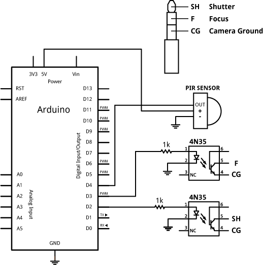
I made a relatively simple attachment to my Canon SLR to create a motion activated camera using Arduino. A lot of this was based on and inspired by the intervalometer project at The Honey Jar. I made some changes to his circuit to use a 4N35 optocoupler instead of reed relays. Here is what you will need:
- Canon SLR camera that takes a 2.5mm headphone plug for remote shutter/focus control. I’m using an XSi, but others should work too.
- Arduino board (I used the Duemilanove)
- (2) 4N35 Optocouplers (available through All Electronics as well as others, don’t know if Radio Shack has these)
- 2.5mm stereo headphone plug
- (2) 1k resistors
- Passive infrared motion detector from Parallax
- Extension cable with 3 pin header from Parallax
- Box to put it all in
The motion detector is really sensitive so I cut a small hole in the box to try and and reduce its field of view. This might not be as much of a problem at night, but during the day it would constantly give false positives.
First solder some wires to the 2.5mm headphone plug. Then connect the plug and electronics as shown in the schematic below:
/**********************
Motion Activated Camera
Dan Bridges 2009

For schematics and more documentation see:
http://www.dayofthenewdan.com/projects/motion-camera
**********************/


boolean focus = false;

int shutterPin = 2;
int focusPin = 3;
int PIRPin = 4;

int shutterPressDelay = 200;
int focusPressDelay = 200;
int interPictureDelay = 500;


void setup(){
  pinMode(shutterPin, OUTPUT);
  pinMode(focusPin, OUTPUT);
}

void loop(){
    if (digitalRead(PIRPin)) {
        takePicture();
        delay(interPictureDelay);
    }
}

void takePicture() {
    //If you want the camera to focus first set
    //the focus variable to true.
    if (focus) {
        digitalWrite(focusPin, HIGH);
        delay(focusPressDelay);
        digitalWrite(focusPin, LOW);
        delay(250);
    }
    digitalWrite(shutterPin, HIGH);
    delay(shutterPressDelay);
    digitalWrite(shutterPin, LOW);
}
Intervalometer
The same circuit (minus the PIR detector) can also be used as a standard intervalometer. At some point I’ll probably add a potentiometer and a LCD screen to allow for custom time intervals on the go.